Overview
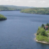
Howard A. Hanson Dam is a U.S. Army Corps of Engineers flood control dam located near the headwaters of the Green River in King County. Its primary purpose is flood control in the winter and fish enhancement in the summer.
Before Howard A. Hanson Dam was constructed, floodwaters of the Green River periodically spread almost unimpeded across the Green River Valley. Over the past 70 years the Valley has flooded more than 30 times, heavily damaging lands and buildings. People still remember the flood of December 1959 when houses were flooded up to the second floors, and much irreplaceable topsoil was washed into Puget Sound. After a tour of the devastated area, the state’s governor was heard to say: “We regard water as one of this state’s greatest assets, but I never quite realized until today how terribly destructive it can be.” It was not until 1961, when Howard A. Hanson Dam went into operation, that the long and disastrous history of major flooding in the Valley was ended.
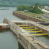
The dam spans Eagle Gorge, a ravine with nearly vertical rock walls. It is an earth and rock-fill structure with a crest length of 450 ft (137.2 m), a total length including spillway and abutments of 675 ft. (205.7 m) and height above bedrock of 235 ft. (71.6 m). The outlet works consist of a gate tower, multi-pier bridge spanning the dam crest and gate tower and spillway. The reservoir extends 7 miles (11.3 km) up the Green River behind the dam and 4 miles (6.4 km) up the North Fork with a total capacity of 106,000 acre-ft (130,753,00 cubic m).
Project Requirements
Numerous studies were undertaken in the 80s and 90s by the Tacoma Water District and the US Army Corps of Engineers to enhance the capacity of the water supply system and lessen the environmental impact of the Dam, one result of these efforts was the Howard Hanson Dam Additional Water Storage Project. A key component of this project is improved fish passage, with the long-term goal being the reintroduction and survival of self sustaining runs of various anadromous fish in the upper Green River watershed area. This means there must be fish passage around the dam. This will be accomplished in two ways, for fish returning to the watershed from the sea a trap and haul technique will be used to transport the fish around the dam, for downstream passage, a state-of-the-art fish passage facility is being constructed. The downstream fish passage facility features include a new intake tower with new fish collection and transport facilities, a wet-well, a floating fish collector, a fish lock, discharge conduit, fish transport pipeline, and monitoring equipment.
What We Did
Excavation of the fish passage facility is being accomplished using controlled drill-and-blast techniques. The excavation is immediately adjacent to the gate tower walls and as close as 26 ft. (8 m) to the outlet tunnel. It is essential that normal and emergency operation of the dam continue throughout construction of the new facility. The US Army Corps of Engineers retained Shannon & Wilson, Inc., a local A&E firm, to design an instrumentation system that would monitor both dynamic and static instrumentation to assess the impact of construction, particularly the blasting, on the existing structure. Instrumentation consists of Geophones, Geokon Vibrating Wire (VW) Crackmeters, Geokon VW Jointmeters, Geokon VW Strain Gages, Geokon VW Rebar Strain Meters, Geokon VW Piezometers, Geokon VW Settlement system and Slope Indicator EL Tiltmeters.
System Design
Shannon and Wilson, working in cooperation with Geokon, Inc., employed us to design and build the Automated Data Acquisition System (ADAS) which would provide this measurement capability. Key features of the system we designed and built:
- Ability to read up to 60 Auto-Resonant VW instruments supplied by Geokon. These are dual-coil vibrating wire instruments, with the addition of Geokons 4500CPR electronic package up to 100 Hz of dynamic response is possible. The sensors and electronics were tested satisfactorily up to 80 Hz. Rack mount assemblies were designed and fabricated by us to house the 4500CPR boards (picture of rack shown at right).
- Ability to sample measurements on each channel with a minimum of 200 Hz. A Dataq Instruments DI-760 was selected, with it’s 250kHz bandwidth this provided ample bandwidth for the maximum number of dynamic channels and the required oversampling.
- Ability to read static instrumentation consisting of standard Geokon vibrating wire instrumentation and Slope Indicator EL Tiltmeters. The static vibrating wire instrumentation was multiplexed using our MultiMux multiplexers with the Geokon 8020-42 Single Coil Adaptor, the Slope EL Tiltmeters were also multiplexed using our MultiMux multiplexers. The DI-760 was used to control the multiplexers. Total static measurement capacity consists of 32 channels of vibrating wire instruments, 16 tiltmeter channels and 48 channels of temperature measurement, using Geokon thermistors (YSI44005 type) or the Slope EL temperature output.
- Creation of MultiLoggerDQ, a modified version our MultiLogger software system, to provide for channel configuration, conversion to engineering units, configuration of triggers (to capture data automatically as a result of blasting), management and operation of simultaneous static and dynamic data capture, integration of our MultiLoggerDB database system and support for viewing dynamic data capture records in our Insite client data access software.


